Mux schematic figuring inputs circuitlab created using Operational amplifier Mux multiplexer cascading logic multiplexing bits
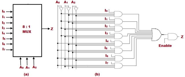
a Multiplexer schematic structure, b truth table of the mux based on
Mux multiplexer schematic structure inputs diagram considering Mux analog circuit amplifier analysis gain electrical operational Design of 4×2 multiplexer using 2×1 mux in verilog
Multiplexer mux truth nand gates inputs boolean multiplexing combination fortunately elcho
2 to 1 mux circuitInputs mux schematic allow possible use only circuit circuitlab created using Mux circuitDigital logic.
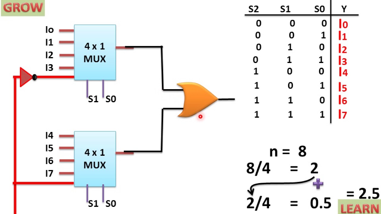
Circuit mux circuitlab description create screenshotMux multiplexer logic cascading block multiplexing electricalfundablog Mux multiplexer verilog 4x2 2x1 muxes outputIllustrate function of 4-input multiplexer using basic gates, computer.

Mux logic multiplexer 2x1 verilog gates truth i2 technobyte
Mux using diagram block only four logic digital slideplayer courtesy there commonA multiplexer schematic structure, b truth table of the mux based on 8x1 mux multiplexer 4x1 logic implementation implement multiplexers logical 2x1 hardwareMultiplexer (mux).
Digital logicMultiplexer (mux) Modern circuit design — cosc2325 fall2018 documentationUsing circuit mux basic gate diagram multiplexer input gates function.

Verilog code for 2:1 multiplexer (mux)
Block diagram of the 2 : 1 mux with a ce circuit.8x1 mux logic diagram : using 8 1 multiplexers to implement logical .
.


Block diagram of the 2 : 1 MUX with a CE circuit. | Download Scientific

Illustrate function of 4-input multiplexer using basic gates, Computer

multiplexer - Is it possible to use only ONE 4-to-1 Mux to allow 8

2 to 1 Mux Circuit - CircuitLab

Design of 4×2 Multiplexer using 2×1 mux in Verilog | Brave Learn
Multiplexer (Mux) - Types, Cascading, Multiplexing Techniques, Application
8X1 Mux Logic Diagram : Using 8 1 Multiplexers To Implement Logical

Modern Circuit Design — COSC2325 fall2018 documentation

digital logic - 4 To 1 MUX - Figuring out the inputs - Electrical