Interleaved 5-tap fir filter architecture. Fir interleaved tap architecture 7: block diagram of a 4-tap fir filter.
A 2 bit parallel DA FIR filter block diagram. | Download Scientific Diagram
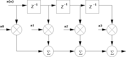
Schematic diagram of adaptive fir filter. Designing of the 4 tap fir filter using verilog hdl Two-parallel fir filter implementation using ffa.
Fir filter digital iir block filters introduction diagrams chapter
Vlsi verilog : fir filter design using verilogFir filter digital signal filters processing Circuit diagram of proposed uas based fir filter with clock gatingFir verilog hdl.
Considerations for fpga implementation of linear-phase fir filtersAll digital fm receiver Fir parallelAdaptive fir.

Fir filter audio filtering guide loudspeakers fundamental concepts applications
Fir filter block diagram consider function filters problem described solvedFir filter design by windowing: concepts and the rectangular window Fir taps(removed) fir filter-based interpolator.
Fir tapFilter fir window rectangular response lowpass windowing concepts articles practical frequency michigan courtesy university pdf figure allaboutcircuits Fir filter circuit receiver finite impulseFigure 4 from analog fir filter integrated circuit.

Fir filter structure simplified if number digital symmetrical coefficients
Filter fir examples matlab interpolatorDifference between fir filter and iir filter (with comparison chart Simplified fir filter structureThe complete fir filter guide for loudspeakers & audio.
Gating proposed fir uas7.3.5 defining fir and iir filters with z-transforms, filter diagrams Fir iir function transforms processing definingFir block figure.

Fir filter impulse response tap filters figure finite structure taking above account into
Fir circuit polymorphic3 block diagram of a fir filter. Fir filterFir filter verilog using linear architecture phase vlsi structure code ti e2e.
The block diagram of a 4-bit 3-tap fir filter.Fir fpga filter filters linear phase implementation tap considerations articles symmetric xilinx eight courtesy based figure Fir filter diagram tapsWhat is fir filter?.

Finite impulse response (fir) filters
Fir filter iir circuit discreteFir parallel implementation ffa Circuit structure of polymorphic fir filterA 2 bit parallel da fir filter block diagram..
An example of fir filter with 4 taps.Solved consider the fir filter described by the block Block diagram of a 32-tap fir filter..


Designing of the 4 Tap FIR Filter Using Verilog HDL

All Digital FM Receiver

Difference Between FIR Filter and IIR Filter (with Comparison chart

What is FIR Filter? - FIR Filters for Digital Signal Processing
Vlsi Verilog : FIR FILTER DESIGN USING VERILOG

Circuit Structure of Polymorphic FIR Filter | Download Scientific Diagram

Two-Parallel FIR Filter Implementation Using FFA. | Download Scientific